
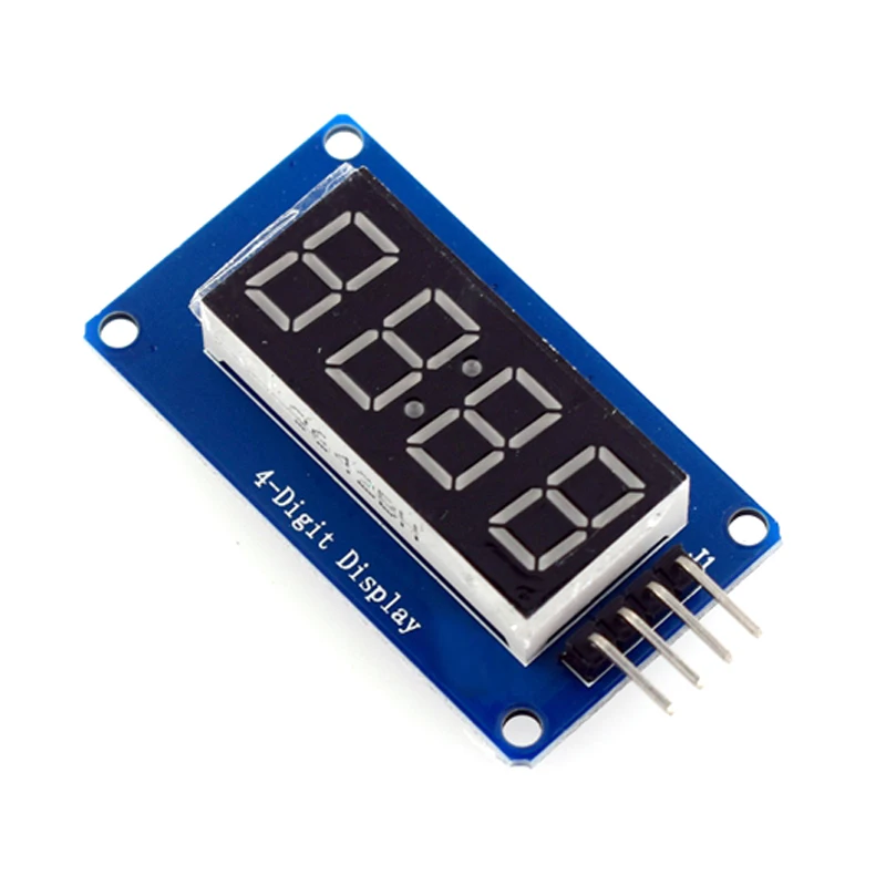
TM1637 LED Display Module 4-Bit Digital Tube


TM1637 LED Display Module 4-Bit Digital Tube
The TM1637 4-Digit LED Display Module provides a simple and efficient method of displaying numerical information using only two communication lines.
Key Features:
- 4-digit 7-segment LED display
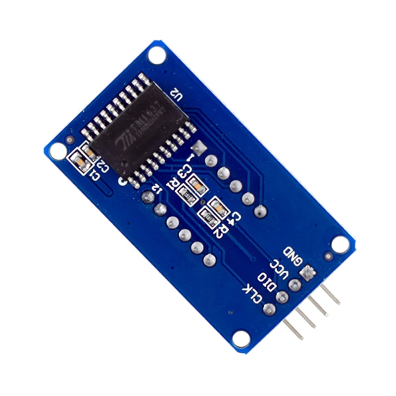
- TM1637 driver IC
- Integrated clock colon indicator
- Simple 2-wire communication interface
- Adjustable brightness control
- Compact module design
What's in the Box:
- 1x TM1637 Display Module
Best suited for: Digital clocks, countdown timers, scoreboards, and measurement displays.
TM1637 LED Display Module For Arduino 7 Segment 4-Bits 0.36Inch Red Anode Digital Tube LED brightness adjustable with clock hour
DESCRIPTION:
TM1637 is a specialized circuit for LED (Light Emitting Diode Display) driver control with keyboard scanning interface. It integrates MCU+digital interface, data latch, LED high-voltage driver, keyboard scanning and other circuits internally. Can be applied to display screen drivers for induction cookers, microwave ovens, and small household appliances.
The module features are as follows:
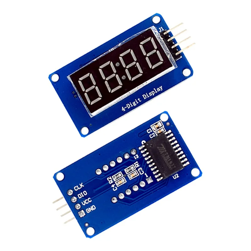
Display device is 4-digit yang red digital tube
Digital tube 8-level grayscale adjustable
Control interface level can be 5V or 3.3V
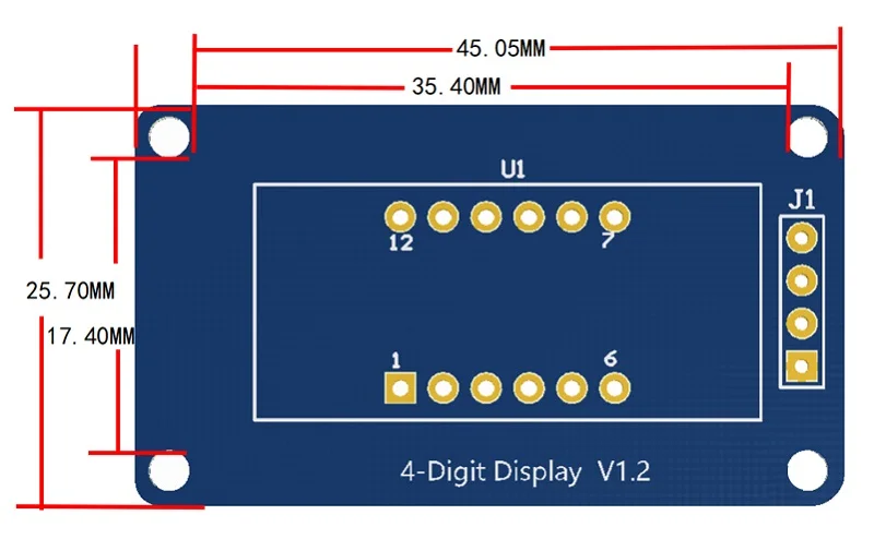
4 M2 screw positioning holes for easy installation
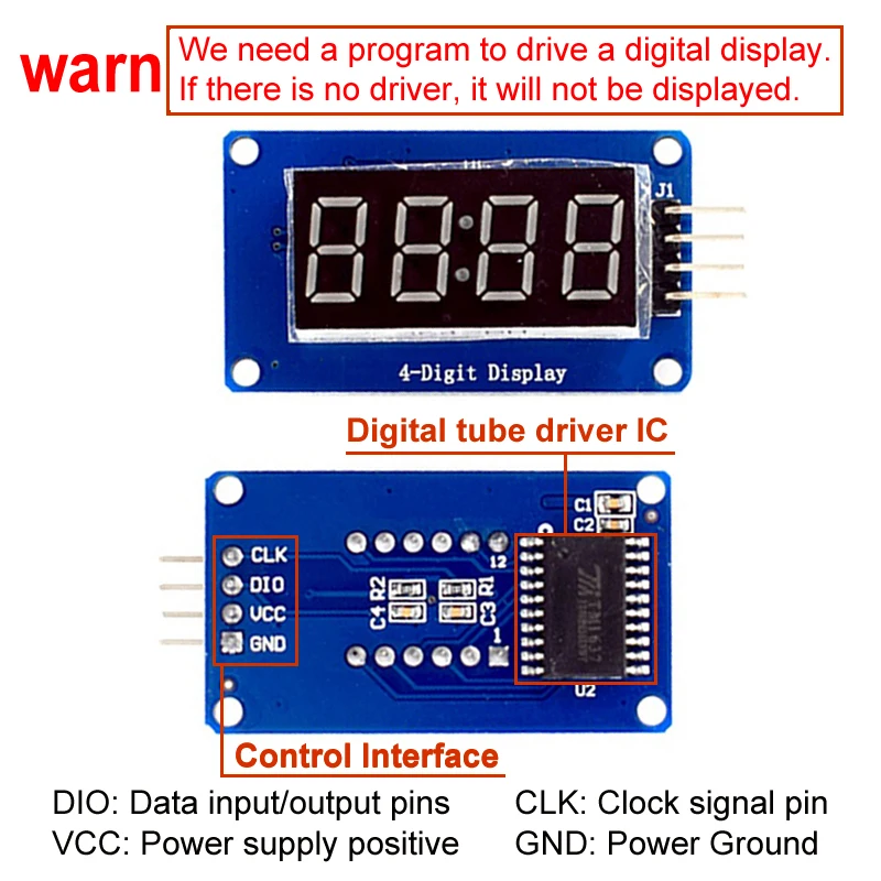
Control interfaceA total of 4 pins (GND, VCC, DIO, CLK), GND is ground, VCC is the power supply, DIO is the data input and output pin, CLK is the clock signal pin;
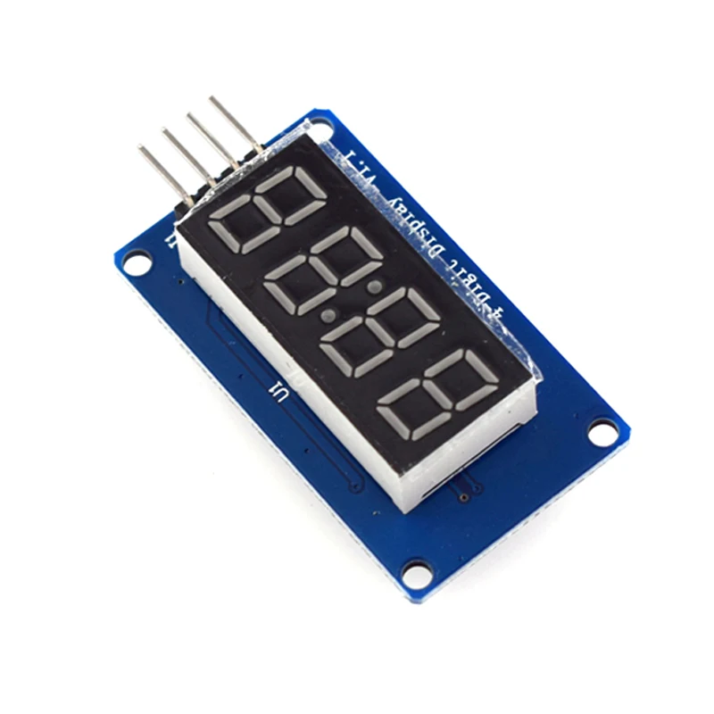
Digital Tube: 4-digit common anode with a 0.36-inch digital tube with a score point, highlighted in red;
Positioning hole: 4 M2 screw positioning holes, the hole diameter is 2.2mm, which makes the module easy to install and position, and realize the module combination;
Overview of the library routines:
1. ClockDisplay: Use the timer 1 of the MCU on the motherboard to time and let the 4-digit display display.
2. NumberFlow: 0~9, A, b, C, d, E, F and other 16 characters flow from right to left.
3. StopWatch: Use the timer 1 of the MCU on the motherboard to time, and use the button to realize the stopwatch function.
Experiment equipment:
An Ard uino compatible motherboard Cat duino (not familiar with open source hardware can be understood as the Atmega328P microcontroller development board) and a mini USB cable;
1 4-digit digital tube display module;
4 male to female DuPont lines for connecting the control interface of the module and the Cat duino development board;
Experimental procedure:
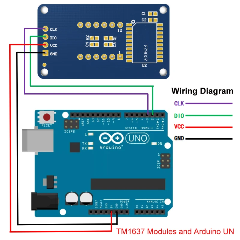
1. Use 4 male to female DuPont lines 4-digit digital display module Connected to Cat duino, as shown in the following table and figure
2. Connect the Catduino with mini USB. If you are using the motherboard for the first time, its USB to serial driver can find the USB Drivers from the drivers in the Ard uino IDE directory.
3. Reopen the Ard uino IDE and click the Open button on the toolbar to open the NumberFlow routine in DigitalTube.
Select the serial port, board name, click the Burn button, you can burn. This routine can make 16 characters from 0~9, A, b, C, d, E, F, etc. flow from right to left.
The function of adjusting the gray scale of the digital tube is the set() function in the class TM1637, and the input parameter is 0~7. The larger the number, the higher the brightness.
Details
This product is crafted with quality materials to ensure durability and performance. Designed with your convenience in mind, it seamlessly fits into your everyday life.
Shipping & Returns
We strive to process and ship all orders in a timely manner, working diligently to ensure that your items are on their way to you as soon as possible.
We are committed to ensuring a positive shopping experience for all our customers. If for any reason you wish to return an item, we invite you to reach out to our team for assistance, and we will evaluate every return request with care and consideration.


